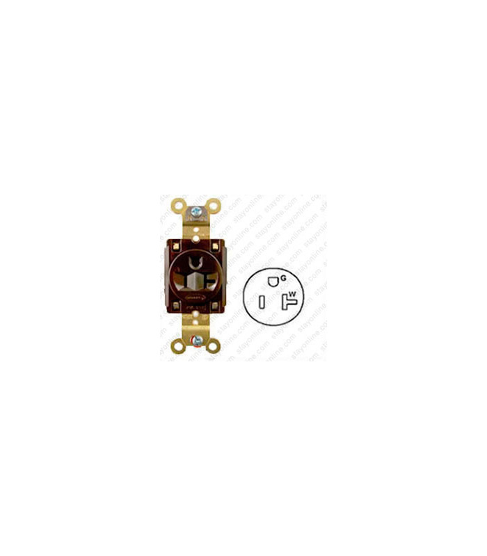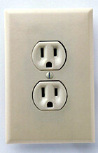
These outlets were precursors to the 'double T' type combination outlet, which is incidentally another obsolete design, for the same reason. This is the type of plug that went into that outlet. Looks a bit different in detail than a recent 2-15, but they are actually still physically compatible. These plates have three T-slots for use with T-slot nuts, bolts, and setup studs. Fixturing Tables Add components such as clamps, brackets, stops, rests, mounting plates, fixturing squares, risers, and V-blocks to build fixtures for welding and assembly.
Author: Terry Peterman What exactly is a kitchen split receptacle circuit, and why the confusion with this common household wiring configuration? I received an e-mail from a website visitor who was wondering if there was a problem with a counter outlet in her home. I answer her question in the following video, article and wiring diagram below:
Question Regarding a Kitchen Split Receptacle Circuit:

Q: We have an electrical outlet that has 240 to one plug and the other plug has 120. There are three wires involved in this counter top plug; red white and black.
Red plus white = 120 volts
White plus black = 120 volts
Black and red = 240 volts! Ouch!
Any idea on how to fix? – Trish
Understanding the Kitchen Split Receptacle Circuit:
Trish, what you have is actually a perfectly normal situation which meets the code rules in many electrical jurisdictions. This is what is known as a split receptacle kitchen circuit.
It is fed by a 2-pole, 15A circuit breaker, and uses 14/2 cable. In this situation, the neutral is shared between the two hot wires (red and black) that come from the panel.

You are correct in that you do have 240V between the black and the red conductors. However, the receptacle is wired so as to only have 120V in each half of the duplex receptacle, and the brass tab is broken between the top and the bottom half of the receptacle on the hot (brass) side of the device, but remains intact on the neutral side. This way the two circuits that feed this outlet “share” the neutral connection.
Kitchen Split Receptacle Circuit Wiring Diagram:

These outlets were precursors to the 'double T' type combination outlet, which is incidentally another obsolete design, for the same reason. This is the type of plug that went into that outlet. Looks a bit different in detail than a recent 2-15, but they are actually still physically compatible. These plates have three T-slots for use with T-slot nuts, bolts, and setup studs. Fixturing Tables Add components such as clamps, brackets, stops, rests, mounting plates, fixturing squares, risers, and V-blocks to build fixtures for welding and assembly.
Author: Terry Peterman What exactly is a kitchen split receptacle circuit, and why the confusion with this common household wiring configuration? I received an e-mail from a website visitor who was wondering if there was a problem with a counter outlet in her home. I answer her question in the following video, article and wiring diagram below:
Question Regarding a Kitchen Split Receptacle Circuit:
Q: We have an electrical outlet that has 240 to one plug and the other plug has 120. There are three wires involved in this counter top plug; red white and black.
Red plus white = 120 volts
White plus black = 120 volts
Black and red = 240 volts! Ouch!
Any idea on how to fix? – Trish
Understanding the Kitchen Split Receptacle Circuit:
Trish, what you have is actually a perfectly normal situation which meets the code rules in many electrical jurisdictions. This is what is known as a split receptacle kitchen circuit.
It is fed by a 2-pole, 15A circuit breaker, and uses 14/2 cable. In this situation, the neutral is shared between the two hot wires (red and black) that come from the panel.
You are correct in that you do have 240V between the black and the red conductors. However, the receptacle is wired so as to only have 120V in each half of the duplex receptacle, and the brass tab is broken between the top and the bottom half of the receptacle on the hot (brass) side of the device, but remains intact on the neutral side. This way the two circuits that feed this outlet “share” the neutral connection.
Kitchen Split Receptacle Circuit Wiring Diagram:
Because the two circuits are from opposite sides of the panel, the neutral will only carry the unbalance load. So if you are using a toaster plugged into the top half, and it is using 8A on circuit #1, and the coffee maker plugged into the bottom half using 6 amps, then the neutral will only be carrying 2 amps of current back to the panel. The maximum that the neutral conductor will carry on a circuit like this is the maximum that one of the appliances that are plugged in will draw.
The new code now requires all kitchen receptacles to be protected by ground fault circuit interrupter (GFCI) receptacles, and must have at least two 20A circuits supplying general purpose kitchen receptacles.
Split kitchen receptacles are still quite common, and are still allowed in some jurisdictions. However, where the new code rules have been adopted, the existing installations are grandfathered and are not and will not be mandated to be rewired. I personally like the kitchen 3-wire circuits as I think they offer more flexibility on counter top appliance locations and configurations with plenty of capacity to supply the various power requirements. However, the complicating issue and change motivating factor was the requirement for GFCI protected outlets in the kitchen area, and protection of split circuitry is more complicated and more expensive to achieve than using 20A GFCI receptacles with feed-through capability.
Not sure about tackling this yourself? Remember: Can’t do it yourself? Get help from a qualified electrical contractor/
Double T Slot Receptacle Wiring
Related posts:

